Table of Contents
Topology Description Language
We introduce topdl (topology description language) as the language for topology description. Our goal is to have a resource independent representation of communicating elements that can be used for experimentation. The basic model underlying topdl is a set of abstract elements that can communicate. To represent topologies at the level of detail that testbeds need to allocate resources and configure hardware, simple topdl descriptions are specialized by adding attributes.
Topdl is testbed independent and, in principle, different testbeds may treat the same topdl slightly differently. Different testbeds may interpret attributes differently. This document will explain how DETER tools interpret the topdl in an effort to encourage interoperability,
There are two primitives in topdl:
- Elements
- Active resources in the experiment: computers, routers, devices that are programmable. These are subclassed for common kinds of elements
- Substrate
- A communications medium to which elements have access. This may be a wired LAN, a shared communication frequency, or may represent the fact that the elements share a line of sight.
The point of contact between these primitives is:
- Interface
- An indication that a particular element can communicate on one or more substrates. An interface appears on exactly one element.
These are deliberately unconstrained, but are an attempt to capture the idea that most network experiments are about things that can talk to other things in constrained ways.
Each subclass and substrate has parameters which set the specifics of that object. For example, the computer subclass of elements can be parameterized by the operating system, the CPU information, the required software, and the storage (memory, disk, etc) that are required. Additional attribute/value pairs (strings) can be attached to the computer (and to some of the parameters) to specialize it for specific access controllers or other applications.
Substrates and interfaces can also have attributes attached, but are characterized by the communication capacity and latency of the substrate, though neither needs to be specified if unimportant.
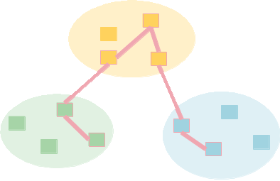
By specializing these primitives, topdl can represent many network topologies. A traditional enterprise configuration can be represented as computer elements for each desktop connected by substrates that represent the LANs that are also interfaces to routers and firewalls that model the system. A system of nodes sharing the same wireless infrastructure share interfaces on the same wireless substrate. Machines that can talk on more than one substrate using the same interface - for example a multi-frequency radio - are specified with one interface on several substrates, one for each frequency of interest.
Representation
This section describes what one can say in topdl. We will be looking at the low-level encoding of the structures, but few experimenters write topdl directly. We have programmatic libraries and facilities to translate from other representations. We believe it is helpful to see the basic structures.
Topdl is encoded in XML. Each substrate and element are encoded as XML elements with interfaces encoded in the elements. Attributes are attached to any of the XML elements. A full XSD encoding is available for qutomatically generating access code.
This section will illustrate the encoding through some simple examples.
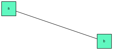
This simple, two-computer topology:

Can be represented in topdl as:
<experiment>
 <version>1.0</version>

 <!-- Substrate that links the two computers -->
 <substrates>
  <name>link0</name>
 </substrates>


 <!-- A computer element named a with an interface on the link0 substrate -->
 <elements>
  <computer>
   <name>a</name>
   <interface>
    <substrate>link0</substrate>
    <name>inf000</name>
   </interface>
  </computer>
 </elements>

 <!-- A computer element named b with an interface on the link0 substrate -->
 <elements>
  <computer>
   <name>b</name>
   <interface>
    <substrate>link0</substrate>
    <name>inf000</name>
   </interface>
  </computer>
 </elements>
</experiment>
That file is attached to this page.
Substrates
That topdl represents a very simple representation of the network, with most of the details unbound. Both substrates and elements can be described in more detail. We start with substrates.
One can extend the representation above by adding parameters to the substrate. To specify that the interconnection is a 100Mbps link, we add the substrate capacity parameter to link0:
<!-- excerpt -->

 <substrates>
  <name>link0</name>
  <capacity>
    <rate>100000.0</rate>
    <kind>max</kind>
  </capacity>
 </substrates>

<!-- excerpt -->
In general, substrates are parameterized by:
- Name
- A unique name to tie interfaces to this substrate.
- Capacity
- The rate of information exchange on this substrate. May be given as an average or peak rate.
- Latency
- The time required for information to cross this substrate. May be an average or a peak.
An interface may also have those parameters, in which case the element to which the interface is attached is limited by the lower of the interface or substrate values. Corner cases, such as a maximum less than an average are dealt with as errors by the system taking the topology as input.
Only the name is required.
Elements
Elements are sub-classed and each subclass has more parameters defined. Extending our example further, an experimenter can choose an operating system - e.g. Ubuntu Linux 12.04 (kernelversion 3.0.0.26) for a computer:
<!--excerpt -->
<!-- A computer element named a with an interface on the link0 substrate -->
 <elements>
  <computer>
   <name>a</name>
   <interface>
    <substrate>link0</substrate>
    <name>inf000</name>
   </interface>
   <os>
     <name>Linux</name>
     <version>3.0.0.26</version>
     <distribution>Ubuntu</distribution>
     <distributionversion>12.04</distributionversion>
   </os>
  </computer>
 </elements>
<!--excerpt -->
Computer
Computers are the most common element subclass used by DETER. They are parameterized by:
- Name
- An identifier for the computer, primarilty useful to researchers directly.
- CPU
- They type and number of CPUs required
- Operating System
- Including version, distribution
- Storage
- Amount of persistent and transient storage - usually disk and memory, but new technologues are possible.
- Software
- The software to install and the location in the file system. A URI may be given for the software distribution.
- Interfaces
- See below
All these parameters, except the name, are optional.
Segment
A sgement is an allocation (or future allocation) of resources to a federated experiment, researchers rarely use these directly, but they are included as an example of a non-computer element. They are useful placeholders in establishing connectivity across a federant that acts as a transit network provider between federants. The optional parameters include:
- Name
- Name of the segment. Primarily useful to reserachers or debuggers.
- Type
- Access controller type, e.g., emulab.
- URI
- The URI at which the access controller can be found.
- Interfaces
- See below
Interfaces
Interfaces are attached to elements. Each is parameterized as follows:
- Name
- A unique name for the interface. (Unique within the interface)
- Substrates
- A list of substrate names to which the interface is attached
- Capacity and Latency
- These are overrides to the substrate values, as described above. Both are optional.
Attributes
The parameters above cover many of the common cases for describing topology elements, but it is helpful to allow applications to attach inormation to topology descriptions, either for tehir use or for the testbed to interpret. Elements, substrates and interfaces can all have attributes directly attached to them. In fact, many parameters and parameter blocks can have attributes attached as well.
Attribues are name/value pairs attached to a topdl entity. There is no limit as to how many can be attached, but each must have a unique name per entity. APplications are encouraged to prefix attributes with their application name.
We list some attributes currently respected by the DETER toolchains.
Attribute Conventions
Though we expect attribute conventions to evolve, currently the following entension attributes are understood. Several are being used to bridge from the existing experiment description language to current topdl, and are somewhat DETER-specific.
These are attributes of Computers:
- failureaction
- What the underlying testbed should do if this node cannot be reserved or configured. Choices are fatal or nonfatal.
- startup
- The startup command to run when the node is booted
- testbed
- The testbed on which to place this element if the experiment is federated.
- type
- The local emulab machine type. This will become less common as more plugins are capable of mapping from CPU/storage parameters into local machine type, but can be used as a low-level escape.
These are attributes of Interface objects nested inside computers:
- ip4_address
- The IP version 4 address of the interface that the attribute is attached to as a dotted decimal.
- ip4_netmask
- The IP version 4 network mask of the interface that the attribute is attached to as a dotted decimal.
Finally, this is an attribute of an Operating System object, nested inside a Computer:
- osid
- The local emulab operating system image. This will become less common as more plugins are capable of mapping from operating system parameters into local image name, but can be used as a low-level escape.
Working With Topdl
First, for many applications, including the federation system and the containers system, most of the functionality is accessible without writing topdl directly. Both of those systems accept extended ns2 experiment descriptions that suffice for much of their functionality. Montage generates topdl internally as well. Researchers primarily need to work with topdl when extending tools or writing local tools. One can either generate experiment descriptions using the DETER ns2 system or by using our topdl library.
Generating Topdl from Ns2
The fedd_ns2topdl.py command is a simple way to generate topdl from a programmatic interface. It is installed on users.isi.deterlab.net. The same ns2 commands that can be used to generate a physical DETER topology are input to fedd_ns2topdl.py. That command strips the event system actions and outputs the topology encoded in topdl.
fedd_ns2topdl.py does not format the XML for easy reading by humans. We recommend using a filter like xmlformat, which is also installed on users to format the topdl for reading or editing.
The two node topology similar to the above can be generated by running this ns2 code through fedd_ns2tpodl.py. You can download and try that code on users.
set ns [new Simulator]
source tb_compat.tcl


set a [$ns node]
set b [$ns node]

set link0 [ $ns duplex-link $a $b 100Mb 0ms DropTail]

$ns rtproto Static
$ns run
fedd_ns2topdl.py includes some additional attributes that the example topdl above does not include. They are described in the attribute conventions section.
Note that DETER's ns2 has extensions that allow most of the topdl constructs to be expressed in ns2 and converted to topdl as above. In addition, both the federation and containers systems take input in the extended ns2 format.
Generating and Manipulating Topdl using Python
The topdl library is a set of python classes and function s that are fully documented elsewhere. This section gives a few examples that gives the feel for the library. All the attached code will run on users.
Each entity is represented by a class with attributes named and broken down as described above. There are routines to import and export topologies in topdl as well as to translate between several formats, including ns2 and GENI Rspecs.
The following python prints the example topdl above:
#!/usr/bin/env python

from deter import topdl

top = topdl.Topology(substrates=[ topdl.Substrate(name='link0')],
        elements=[
            topdl.Computer(name='a', interface=[
                topdl.Interface(name='inf000', substrate=['link0'])]
            ),
            topdl.Computer(name='b', interface=[
                topdl.Interface(name='inf000', substrate=['link0'])],
            )]
        )
print topdl.topology_to_xml(top, top='experiment')
That code constructs the small topology entirely from constructors, which is impractical for large topologies. This code breaks the construction into a couple loops, which are easier to build on and understand. Output is identical.
#!/usr/bin/env python

from deter import topdl

subs = [ ]
elems = [ ]

subs.append(topdl.Substrate(name='link0'))

for elem_name in ('a', 'b'):
    inf = topdl.Interface(name='inf000', substrate=['link0'])
    elem = topdl.Computer(name=elem_name, interface=[inf])
    elems.append(elem)

top = topdl.Topology(substrates=subs, elements=elems)

print topdl.topology_to_xml(top, top='experiment')
There are also routines for changing existing topologies. The following example numbers the computers in a topology by adding a "computer_number" attribute to them and prints the topology in topdl.
#!/usr/bin/env python

import sys
from deter import topdl

if len(sys.argv) < 2:
    sys.exit('Usage: %s topdl_file' % sys.argv[0])

top = topdl.topology_from_xml(filename=sys.argv[1], top='experiment')

for i, e in enumerate(top.elements):
    if not isinstance(e, topdl.Computer): continue
    e.set_attribute('computer_number', '%s' % i)


print topdl.topology_to_xml(top, top='experiment')
When run on the example topdl and formatted, the output looks like this - with comments added to hilight the new attributes.
<experiment>
 <version>1.0</version>
 <substrates>
  <name>link0</name>
 </substrates>
 <elements>
  <computer>
   <name>a</name>
   <interface>
    <substrate>link0</substrate>
    <name>inf000</name>
   </interface>

   <!-- Here is an added attribute -->
   <attribute>
    <attribute>computer_number</attribute>
    <value>0</value>
   </attribute>
   <!-- end of added attribute -->

  </computer>
 </elements>
 <elements>
  <computer>
   <name>b</name>
   <interface>
    <substrate>link0</substrate>
    <name>inf000</name>
   </interface>

   <!-- Here is an added attribute -->
   <attribute>
    <attribute>computer_number</attribute>
    <value>1</value>
   </attribute>
   <!-- end of added attribute -->

  </computer>
 </elements>
</experiment>
More details are available in the library documentation
Attachments (6)
-
two.png (3.6 KB) - added by 12 years ago.
two node topology
-
two.xml (626 bytes) - added by 12 years ago.
Simple topdl example file
-
example1.py (391 bytes) - added by 12 years ago.
Python topdl example
-
example2.py (396 bytes) - added by 12 years ago.
Python topdl example
-
example3.py (394 bytes) - added by 12 years ago.
Python topdl editing example
-
two.tcl (164 bytes) - added by 12 years ago.
ns2 example for fedd_ns2topdl.py
Download all attachments as: .zip